ZF 8HP
Models
Caution
Currently, only 8HP models with 16 pin connectors are compatible. Models with only 10 pins do not have the required IO to allow an external TCM.
| Model | Support | Comment |
|---|---|---|
| 8HP45 | Y | Gen 1 |
| 8HP50 | Y | Gen 2 |
| 8HP51 | N* | Gen 3 *Requires Gen 2 valve body |
| 8HP70 | Y | Gen 1 |
| 8HP75 | Y | Gen 2 |
| 8HP76 | N* | Gen 3 *Requires Gen 2 valve body |
| 8HP90 | Y | Gen 1 |
| 8HP95 | Y | Gen 2 |
Base Calibration
A base calibration based on the 8HP70 is included with MectriCal. Solenoid pressure translation tables are also included separately.
Wiring
Mechatronics Modifications
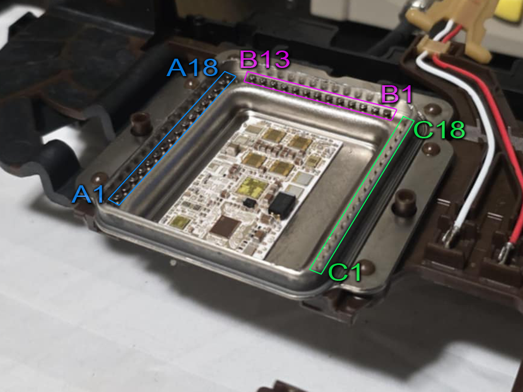
In order to control the 8HP transmission, the internal mechatronics unit must be bypassed and the control signals routed externally.
- Remove the mechatronics assembly from the transmission.
- Cut the lid off the OEM TCM enclosure.
- Cut all the fine wire connections between the OEM TCM and the interface pads.
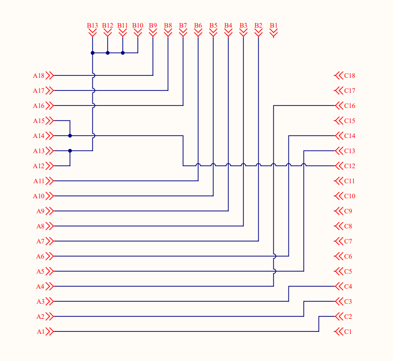
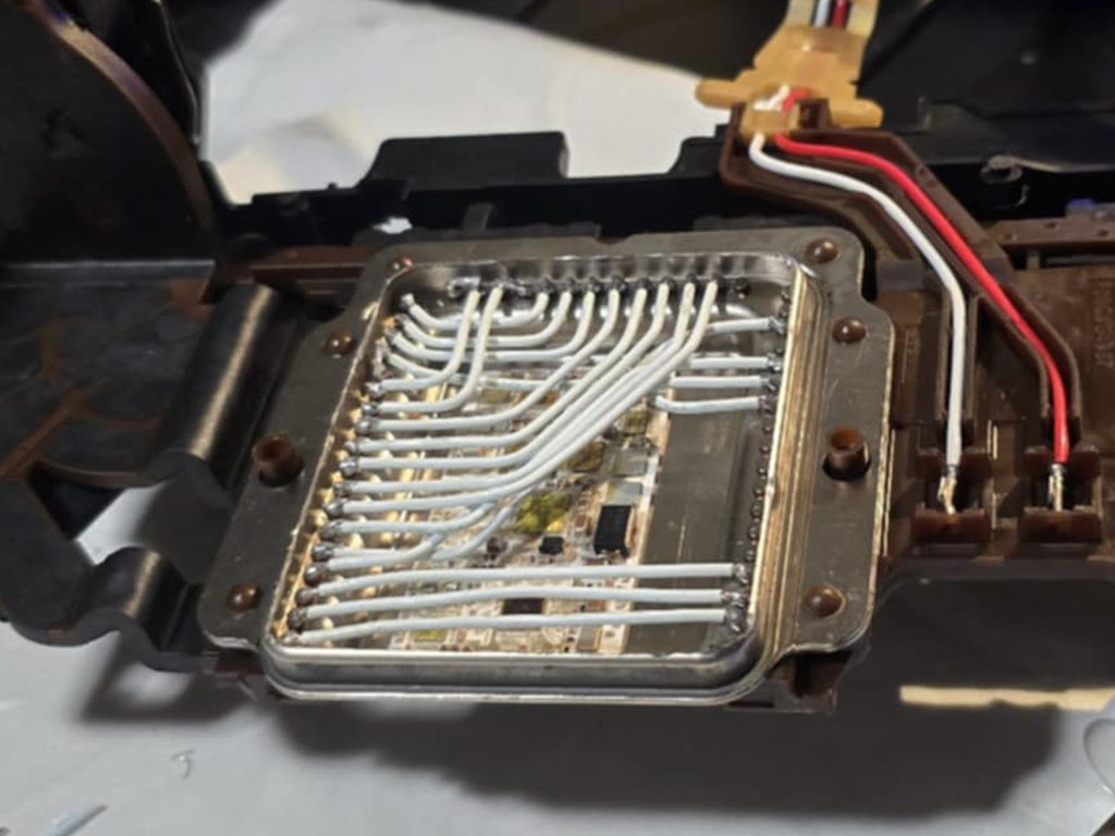
- Wire connections between pads as follows…
Caution
22 AWG or 24 AWG Tefzel wire should be used to bridge connections as it can withstand the temperatures and oil present inside the transmission.
For simplicity and compatibility we’re using the same pin designations as the DomiWorks 8HP Wiring Kit.
| IO Pin (A) | Internal Pin (B/C) |
|---|---|
| A1 | C2 |
| A2 | C3 |
| A3 | C4 |
| A4 | C16 |
| A5 | C13 |
| A6 | C14 |
| A7 | B2 |
| A8 | B3 |
| A9 | B4 |
| A10 | B5 |
| A11 | B6 |
| A12 | B10, B11, B12, B13 |
| A13 | B10, B11, B12, B13 |
| A14 | C12 |
| A15 | C12 |
| A16 | B7 |
| A17 | B8 |
| A18 | B9 |
Potting
We have found that potting the modified mechatronics units with compounds such as R125 has resulted in repeated failures. There appears to be a negative interaction between R125 and the oil used in the 8HP transmissions. The most reliable results we have seen have come from NOT potting the internal connections.
Gearbox Connector
Important
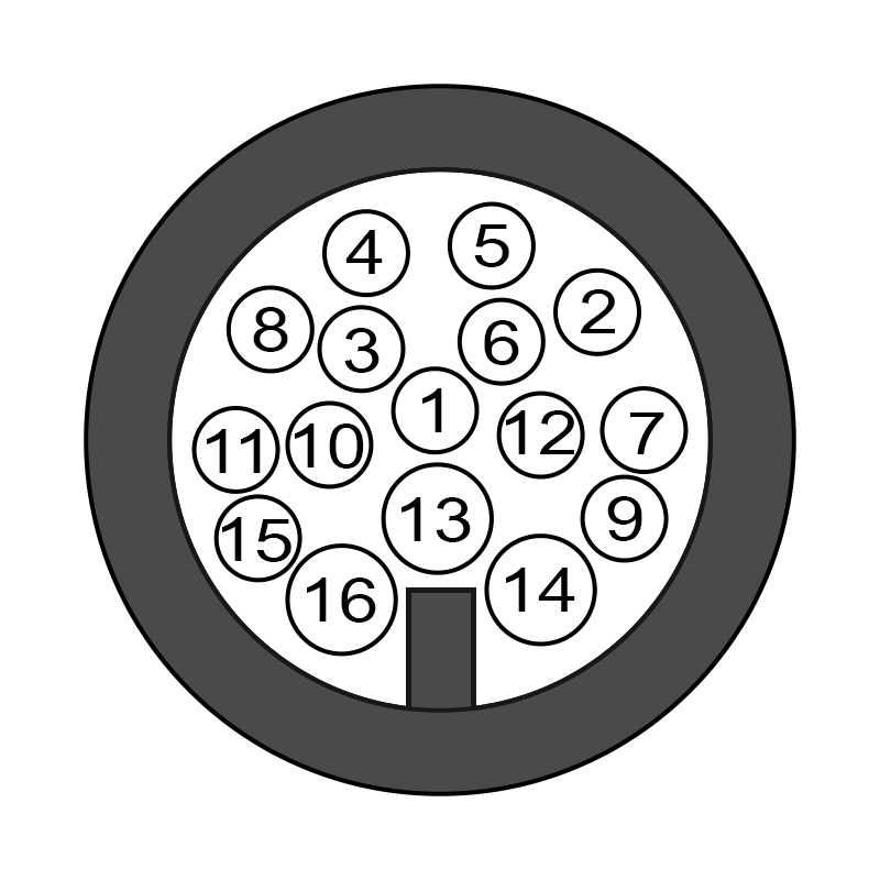
Pinout assumes mechatronic modifications have been completed as detailed above.
| Pin | Function | TCM Pin *1 |
|---|---|---|
| 1 | Sensor 0V Ref | Sensor GND (A9) |
| 2 | Line Pressure Solenoid | Sol 2 (B11) |
| 3 | Speed Sensor 8V Supply | 8V Out (C18) |
| 4 | Accumulator Solenoid | Sol 10 (B19) |
| 5 | Park Hold Solenoid | Sol 9 (B18) |
| 6 | Park Release Solenoid | Sol 1 (B10) |
| 7 | Clutch C Solenoid | Sol 4 (B13) |
| 8 | Input Shaft Speed Signal | DI 4 (A18) |
| 9 | Clutch E Solenoid | Sol 5 (B14) |
| 10 | Output Shaft Speed Signal | DI 5 (A19) |
| 11 | Brake A Solenoid | Sol 8 (B17) |
| 12 | TC Lockup Solenoid | Sol 3 (B12) |
| 13 | Trans Fluid Temp Sensor | An 1 (A1) |
| 14 | Solenoid Power Supply | Sol +V Out (B30+B31) *2 |
| 15 (Gen 1) | Brake B Solenoid | Sol 6 (B15) *3 |
| 15 (Gen 2) | Clutch D Solenoid | Sol 6 (B15) *3 |
| 16 (Gen 1) | Clutch D Solenoid | Sol 7 (B16) *3 |
| 16 (Gen 2) | Brake B Solenoid | Sol 7 (B16) *3 |
1. This pinout matches the supplied 8HP base calibration. You’re free to alter the TCM pin assignments as long as the change is reflected in the config.
2. Ideally each 4 solenoids would have a separate supply bank, but this isn’t possible using the OEM connector. Connecting to two bridged solenoid supplies will suffice.
3. To cater for Gen 1 vs Gen 2, swap the Brake B / Clutch D solenoid assignment in config OR swap pins 15 / 16 in the wiring harness.
Speed Sensors
- Input Shaft Speed
- Output Shaft Speed
The sensors are 2-wire hall effect type, however the polarity of the internal wiring means the dedicated hall sensor inputs on the TCM cannot be used. Instead, the sensors can be wired to Digital Inputs 1 to 8. The internal 330R pulldown must to be enabled.
In this arrangement, the signal voltage will sit at around 2V when stationary, and pulse up to around 4V when a tooth passes the sensor.
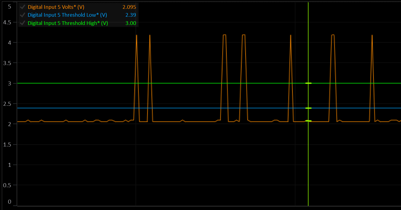
The high and low arming thresholds must be set correctly to detect the speed signal. The low threshold must be ABOVE the sensor voltage at rest, and the high threshold must be BELOW the maximum voltage when the sensor is active.
Solenoids
The ZF 8HP contains nine solenoids. All but the park-release/hold solenoids are Variable‐Force Solenoids (VSF). The park‐release and park‐hold are on/off.
Shift Elements
The 8HP uses the following “shift elements”:
- Two fixed multidisc brakes (brake A and B)
- Three rotary multidisc clutches (clutch C, D and E).
The multidisc clutches (C, D and E) feed the drive torque to the planetary gear. The multidisc brakes (A and B) support the torque against the transmission housing.
| Solenoid | Shift Element | Note |
|---|---|---|
| Clutch Solenoid A | Brake A | VFS, normally vented (no pressure when off). |
| Clutch Solenoid B | Brake B | VFS, normally vented (no pressure when off). |
| Clutch Solenoid C | Clutch C | VFS, normally applied (high pressure when off). |
| Clutch Solenoid D | Clutch D | VFS, normally applied (high pressure when off). |
| Clutch Solenoid E | Clutch E | VFS, normally applied (high pressure when off). |
Line Pressure Solenoid
VFS, normally applied. Modulates the valve-body pressure regulator to maintain the transmission’s main hydraulic (line) pressure under all operating conditions.
Torque Converter Clutch (TCC) Solenoid
VFS, normally vented. Controls apply pressure to the lock-up piston in the torque converter for smooth lock/unlock transitions.
Park Release Solenoid
On/Off, normally open. When energized, it directs line pressure to the park-release valve to retract the parking pawl, allowing selection of Drive or Reverse.
Park Hold Solenoid
Mechanical. Clips onto and holds the park-release piston in its disengaged position after the pawl is withdrawn. Does not flow hydraulic oil.
Gear Sequencing
By engaging different combinations of the five shift elements listed above, the transmission obtains each of its eight forward ratios (plus reverse).
| Gear | Brake A | Brake B | Clutch C | Clutch D | Clutch E |
|---|---|---|---|---|---|
| P | X | ||||
| R | X | X | X | ||
| N | X | ||||
| 1 | X | X | X | ||
| 2 | X | X | X | ||
| 3 | X | X | X | ||
| 4 | X | X | X | ||
| 5 | X | X | X | ||
| 6 | X | X | X | ||
| 7 | X | X | X | ||
| 8 | X | X | X |
Pressure Control
The 8HP does not have any pressure sensors. This means that all internal pressures are inferred from solenoid current. Because the TCM uses pressure targets it’s important to get the solenoid pressure translations as accurate as possible. The supplied 8HP base calibration includes pressure translation tables taken from OEM roms. In most cases these do not need to be changed.
Optionally, you may enable Line Pressure and/or Clutch Pressure estimations to give feedback based on actual solenoid activity and fluid temperature.