Nissan Stagea M35
This integration package unlocks the Nissan Stagea M35 vehicle integration preset mode in MVIC Firmware. This enables almost any CAN capable aftermarket Engine Management system to be used in the vehicle, while maintaining all OEM functionality.
Features
- Receives all critical vehicle data.
- Receives all critical TCM data including torque reduction requests.
- Mimics the OEM ECU so all vehicle systems continue to function.
- Configurable to Send/Receive any data to almost any aftermarket ECU.
Disclaimer
Nissan Stagea M35
The Nissan Stagea M35 requires that careful attention is paid to torque management to avoid damaging the automatic transmission. This involves ensuring that the end user’s Engine Management System is configured to abide by torque reduction requests and is able to output the required data to keep the vehicle functioning properly. Those requirements are detailed in this document.
Mectric CAN Bus Vehicle Integration
Important Notice:
This integration package is intended for use with Mectric Motorsport Electronics MVIC devices. It is designed to facilitate integration with a vehicle’s CAN Bus system. By using this Vehicle Integration package, you agree to the terms and limitations set forth in this disclaimer.
User Responsibility
- This software is intended for use by trained professionals or individuals with sufficient knowledge of automotive systems and the CAN Bus protocol.
- Improper use, installation, or configuration of the software may result in damage to the vehicle’s electronic or mechanical components, including but not limited to the transmission, engine, or other critical systems.
Warranty Disclaimer
- This product is provided “as is,” without any warranties, express or implied, including but not limited to merchantability, fitness for a particular purpose, or non-infringement.
- Mectric Motorsport Electronics assumes no liability for any damage to the vehicle or its components resulting from the use of this Vehicle Integration package.
Limitation of Liability
- Under no circumstances shall the Mectric Motorsport Electronics, its distributors, or their affiliates be held liable for direct, indirect, incidental, consequential, or special damages arising from the use of this Vehicle Integration, including but not limited to vehicle repair costs, downtime, or loss of data.
Safety Advisory
- Before installing or using this Vehicle Integration, ensure that it is compatible with your vehicle’s make and model.
- Always test the system in a controlled environment before regular use.
- Consult a qualified automotive technician if you are unsure of the installation or configuration process.
Acknowledgement
By using this software, you acknowledge that you have read, understood, and agreed to this disclaimer.
Installation
Minimum MVIC Firmware Version: 1.0.2.9097 – 27/11/24
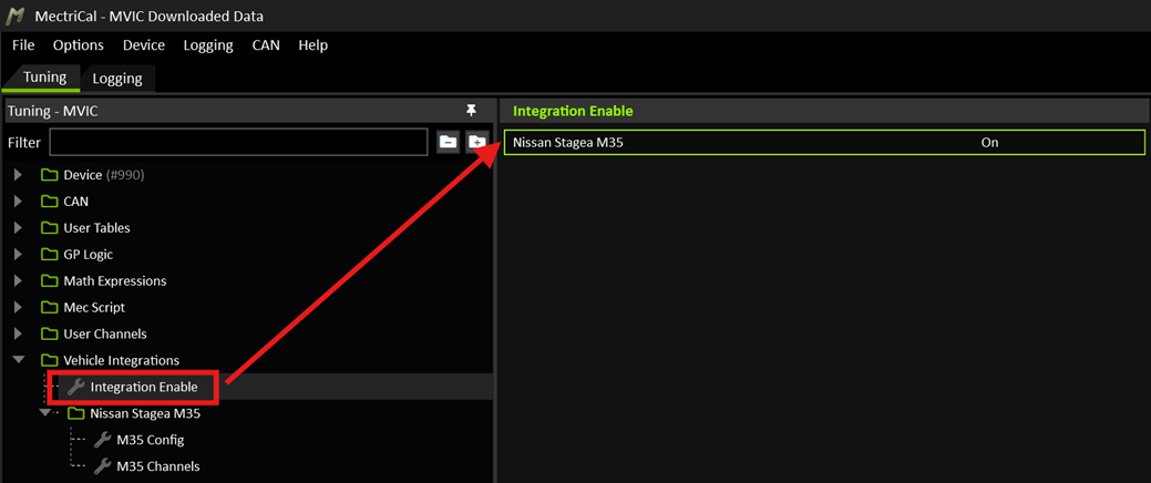
Enable the Nissan Stagea M35 Integration Mode:
Enter the Activation Key provided when you purchased the Vehicle Integration:
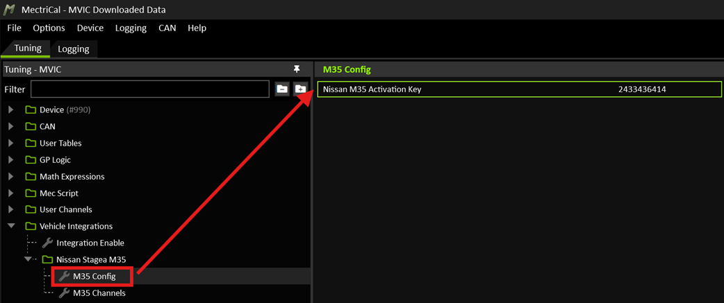
This key is unique for every device serial number.Set a CAN Channel to “Nissan Stagea M35 Vehicle Rx”:
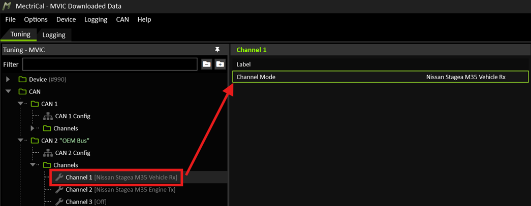 It does not matter which channel is used, as long as it belongs to the CAN Node connected to the vehicle’s OEM Bus.
Set a second CAN Channel to “Nissan Stagea M35 Engine Tx”:
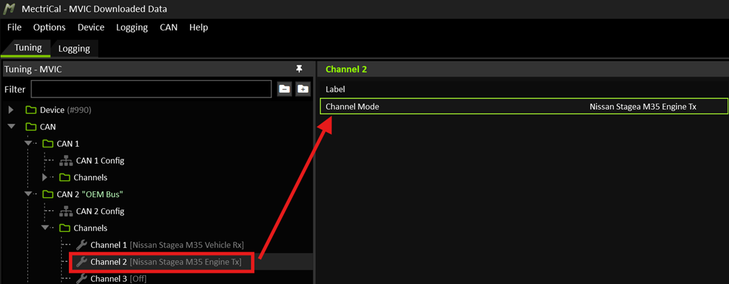 Again, it doesn’t matter channel is used, as long as it belongs to the CAN Node connected to the vehicle’s OEM Bus.
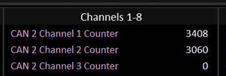
Verify that the chosen CAN Channel Counter runtimes indicate the sending and receiving of data.
Proceed to configure all required communications to your Engine Management System and setup any other required channels, depending on your application. For example:
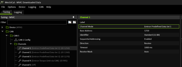
Communications with aftermarket systems can be on a separate CAN Bus network to the OEM bus. It can be beneficial to keep them separate as it allows the two buses to run at different bit rates and keeps the OEM bus’s bandwidth from being compromised.
Note: The OEM CAN Bus runs at 500 Kbps. Most aftermarket CAN bus devices usually default to 1 Mbps. You cannot change the OEM bus speed. The CAN Node connected to the OEM bus (CAN 2 in this example) must set to 500 Kbps.
Vehicle Data
The following channels are received from several vehicle modules including TCM, BCM, and ABS. Some of these will contain critical information that the Engine Management System will need to act on.
TCM Torque Reduction Request
CriticalDuring a gearshift, the TCM will output a positive value on this channel. When this channel is 0, no action is required. When this value is positive, it represents the minimum amount of torque to be reduced. The Engine Management System MUST act on this request immediately and reduce engine torque so that the transmission can change gear safely. See the section on Transmission Torque Management for more info.
Output Values: 0 to 90 Nm
Transmission Low Torque Flag
CriticalThe TCM will issue this flag under a range of conditions. It instructs the Engine Management system that full power should not be used as the transmission is in some state unsuitable for it. It also doubles as a limp home status. For example:
- In Neutral or Park
- When a fault is detected See the section on Transmission Torque Management for more info.
Output Values: 0 or 1 (Off/On)
Gear
The current gear that the transmission is in.
Output Values: 1 to 5; representing Gears 1 through 5 respectively.
Note: Gear will show as 1 when in Neutral.
Next Gear
The next gear that the transmission intends to shift into.
Output Values: 1 to 5, representing Gears 1 through 5 respectively.
Previous Gear
The gear that the transmission recently shifted out of.
Output Values: 1 to 5, representing Gears 1 through 5 respectively.
Gear Request
Represents the gear requested by the driver when in Manual Mode. This doesn’t necessarily represent the gear the transmission is actually in.
Output Values: 1 to 5, representing Gears 1 through 5 respectively.
Gear Selector Status
Represents the position of the gear selector.
Output Values:
- 1 = Park
- 2 = reverse
- 3 = Neutral
- 4 = Drive
- 5 = Manual
Shift In Progress
This flag is issued in advance of a gear shift and clears once the shift has completed. Note this happens well in advance of a torque reduction request. In most applications it does not require any action to be taken and is simply informative.
Output Values: 0 or 1 (Off/On)
Input Shaft Speed
The speed of the transmissions input shaft, post torque converter. This is useful for calculating converter slip.
Output Values: 0 to 8000+ RPM
Output Shaft Speed
The speed of the transmissions output shaft.
Output Values: 0 to 8000+ RPM
Wheel Speed Front Left
The speed of the front left wheel.
Output Values: 0 to 400 Km/h
Wheel Speed Front Right
The speed of the front right wheel.
Output Values: 0 to 400 Km/h
Wheel Speed Rear Left
The speed of the rear left wheel.
Output Values: 0 to 400 Km/h
Wheel Speed Rear Right
The speed of the rear right wheel.
Output Values: 0 to 400 Km/h
Brake Switch
Indicates that the brake pedal is pressed.
Output Values: 0 or 1 (Off/On)
AC Switch
Indicates that the Air Conditioning Switch is on.
Output Values: 0 or 1 (Off/On)
Engine Data
The following channels are transmitted by the MVIC to mimic the OEM ECU. In most cases these channels MUST be sourced from the user’s Engine Management System. In cases where the ECU is incapable of generating and transmitting the data to the MVIC, they will need to be generated in some other way inside the MVIC for the vehicle to function correctly.
Engine Torque (Uncorrected)
CriticalThis is the actual amount of torque the engine can produce, EXCLUDING any reductions or interventions such as retards or cuts.
Torque MUST be represented with a reasonable degree of accuracy for proper transmission operation.
If the ECU cannot calculate this value, then you MUST generate it by some other means such as: MVIC Torque Model, Table, or Math Expression.
Info
MVIC Firmware v1.2.0+ has a mathematical torque model function
Typical Input Values: -100 to 800 Nm
Hints: On an unloaded engine (in neutral): When the engine accelerates the torque will be positive. When the engine decelerates the torque will be negative. When the engine speed is stable, torque will be near zero.
Cruising torque will typically be under 100 Nm. A stock engine would report 300 - 400 Nm at full load.
Engine Torque (Actual)
CriticalThis is the actual amount of torque the engine is producing, INCLUDING any reductions or interventions such as retards or cuts.
Under Normal Conditions: ‘Engine Torque (Actual)’ should follow closely to ‘Engine Torque (Uncorrected)’. On a standard car, when not shifting, these two values are almost identical most of the time.
During a Grear Shift:
The ECU must abide by the ‘TCM Torque Reduction Request’ and reduce engine torque. During this time the reported actual engine torque should reflect reduction in action. It should deviate below the ‘Engine Torque (Uncorrected)’ by at least the amount of the reduction request.
For Example:
- Engine Torque (Uncorrected) = 350 Nm.
- TCM Torque Reduction Request = 90 Nm.
- Engine Torque (Actual) should drop below 260 Nm.
If the ECU cannot calculate this value, then you MUST generate it by some other means such as a Math Expression, Table, or combination of the two. If this channel is calculated, it is up to the end user to guarantee that the ECU is reducing correctly torque when required.
Typical Input Values: -100 to 800 Nm
Engine Speed
The current engine speed.
Typical Input Values: 0 to 8000 RPM
Pedal Position
Drive by wire accelerator pedal position.
Typical Input Values: 0 to 100 %
Throttle Position
Drive by wire throttle position.
Typical Input Values: 0 to 100 %
Air Mass Flow
The mass of air flowing through the engine. This originally comes from the OEM MAF sensor, but many good aftermarket ECU’s will calculate this value as part of their fuel model.
This value can also be calculated from ‘Air Mass Per Cylinder’ using a Math Expression:
AirMassFlow = AirMassPerCyl × NumCyl × (EngineSpeed ÷ 2 ÷ 60)
If there is no ‘Air Mass Per Cylinder’ channel available, you may have to build this channel using a Table.
Typical Input Values: 0 to 800 g/Sec
Hints:
Values in the range of 300-600 g/Sec at full RPM and load would be typical, depending on the engine configuration. A stock engine will report 200-300 g/sec.
Engine Temperature
This is typically equivalent to Coolant Temperature.
Typical Input Values: -20 to 130 °C
Battery Voltage
This channel is generated internally by the MVIC measuring its own supply voltage.
Typical Input Values: 9 to 16 Volts
Ignition Switch
Represents the state of the ignition switch. Typically, this will always be 1 while the ECU is on. If the ECU has a hold power relay this will transition to 0 before the ECU turns off.
The channel can be generated by the MVIC with a General Purpose Logic function.
Typical Input Values: 0 or 1 (Off/On). 1 when the vehicle’s ignition switch is on.
Start Switch
Represents the state of the key in the start position.
The channel can be generated by the MVIC with a General Purpose Logic function. For example: Engine Speed > 0 AND Engine Speed < 400.
Typical Input Values: 0 or 1 (Off/On). Normally 0, 1 when the engine is cranking.
Engine Fan Request 1
Enables the vehicle’s engine fan 1. The ECU should set this channel to 1 to enable the first fan.
The channel can be generated by the MVIC with a General Purpose Logic function. For example: Engine Temperature > 68 AND Engine Speed > 400.
Typical Input Values: 0 or 1 (Off/On)
Engine Fan Request 2
Enables the vehicle’s engine fan 2. The ECU should set this channel to 1 to enable the second fan. This channel should also be set to turn on when the Air Conditioning is on.
The channel can be generated by the MVIC with a General Purpose Logic function. For example: (Engine Temperature > 88 OR AC Switch == 1) AND Engine Speed > 400.
Typical Input Values: 0 or 1 (Off/On)
AC Clutch Status
Enables the vehicle’s Air Conditioning Compressor Clutch. The ECU should set this channel to 1 to enable the AC Compressor.
The Stagea’s ECU needs to fully control the AC system, including monitoring the system pressure. Do not just turn the clutch on whenever the AC Switch is on.
Typical Input Values: 0 or 1 (Off/On)
Overrun Fuel Cut Status
Represents the state of the engine’s ORFC.
The channel can be generated by the MVIC with a General Purpose Logic function. For example: Pedal Position < 2 AND Engine Speed > 1800.
Typical Input Values: 0 or 1 (Off/On)
Engine DTC Count
Represents the number of Detected Trouble Codes present in the ECU.
If the number is greater than zero, the MVIC will set a flag on the stagea’s CAN bus that a fault is present in the engine’s ECU.
Typical Input Values: 0 to 255
Transmission Torque Management
The Stagea’s automatic transmission requires the engine to reduce torque on gearshifts. A request is made for a very brief time which represents the amount of torque to be reduced.
The default channel for this request is TCM Torque Reduction Request. It typically outputs a value between 0 and 90.
The MVIC must report engine torque to the TCM in order for it to apply correct line pressure, and shift scheduling. If the ECU is not able to generate the required torque values, they MUST be generated inside the MVIC instead.
The torque values given to the transmission will greatly affect the way the car drives and how the transmission performs.
Required Channels from the ECU:
Engine Torque (Uncorrected): This is the torque that the engine can produce if no interventions are in place such as retards or cuts.Engine Torque (Actual): This is the actual torque the engine is making, including interventions such as retards or cuts. This value should be inclusive of any frictional loss and should ideally go negative during engine overrun.
Required Channels the ECU must listen to:
TCM Torque Reduction Request: When this channel is greater than 0, the ECU is required to reduce torque by at least this amount.Transmission Low Torque Flag: Whenever this flag is set, the ECU should limit engine torque significantly. This should ideally be done by limiting throttle opening to a “Limp Home” level.
 Note the channel name for the reduction request has since changed to “TCM Torque Reduction Request”.
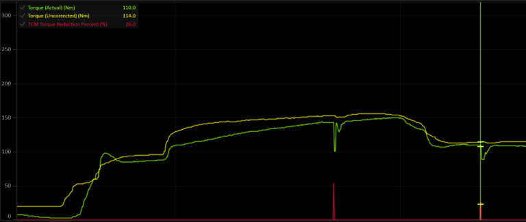
You can see that under normal conditions, uncorrected (yellow) and actual (green) engine torque should follow each other closely. In fact, it’s ok for these values to be identical. When a torque reduction request is made, the actual engine torque must drop by at least that amount, while the uncorrected torque remains unchanged.
Warning
Failure to abide by these torque reduction requests may result in transmission damage!